


TWINFLEX S
|
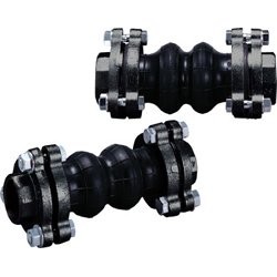
Twin-Sphere Rubber Joint with Floating Flanges TWINFLEX Screwed Type
|
TWINFLEX Screwed Type Rubber Joint can afford large defletion that you can hardly imagine.
It has various functions and are highly reliable.
This double sphere TWINFLEX rubber joint allows increased compression, elongation and angular movement. The unique double sphere design improves noise and vibration isolation and dampens hydraulic surge and shock. Refer to the Product Data Sheets for more information.
Key Benefits
• Compensate for Axial and lateral movement due to thermal changes.
• Isolate noise and vibration from piping system.
• Complete union assembly provided for ease of installation.
• No gasket needed for sealing area.
Typical Application
• TWINFLEX union type joints are used for connecting pipes and equipment where threaded union ends are preferred.
| Operating Conditions | |
| Size Range | 1/2" to 2" |
| Max. Pressure* | 142 psig |
| Operating Temperature | 14°F to 158°F |
| Vacuum Rating* | 25"Hg |
| Burst Pressure* | Greater than 780 psig |
* at normal temperature of 70°F

| Feature |
|
High Efficiency for Vibration and Noise Isolation |
| Applications |
|
● This product is mainly applicable for piping systems in commercial and industrial buildings and plants. |
| Operating Conditions and Performance |
|
● Check if maximum pressure and temperature are within the range of use. |
|
|

|
Structure |
||||||||||||||||||||||||||||||||||||
|
|
||||||||||||||||||||||||||||||||||||
|
|
||||||||||||||||||||||||||||||||||||
|
● The material of No.1,2 and 6 can be changeable to SUS304. |
||||||||||||||||||||||||||||||||||||

| Dimensions and Allowable Movements | ||||||||||||
| Nominal Dia. | Dimension [mm] | Allowable Movement [mm] | Installation Tolerances [mm] | |||||||||
| mm | inch | L | φd | ℓ | T.M | A.E | A.C. | A.M. | T.M | A.E | A.C. | A.M. |
| 15 | 1/2 | 120 | 25 | 30 | 15 | 10 | 15 | 15° | 6 | 3 | 6 | 7.5° |
| 20 | 3/4 | 120 | 25 | 30 | 15 | 10 | 15 | 15° | 6 | 3 | 6 | 7.5° |
| 25 | 1 | 120 | 25 | 30 | 15 | 10 | 15 | 15° | 6 | 3 | 6 | 7.5° |
| 32 | 1 1/4 | 175 | 35 | 35 | 20 | 10 | 20 | 20° | 8 | 3 | 6 | 7.5° |
| 40 | 1 1/2 | 175 | 35 | 35 | 20 | 10 | 20 | 20° | 8 | 3 | 6 | 7.5° |
| 50 | 2 | 175 | 45 | 40 | 20 | 10 | 20 | 20° | 8 | 3 | 6 | 7.5° |
| |
||||||||||||
|
● T.M=Transverse Movement
|
|
|
|
|


| Connection Procedure |
|
 |
 |
| Remove the bolt and disassemble flange A and socket from the main body. |
Put flange A through the counterpart pipe. |
 |
 |
| Screw the socket to the counterpart pipe. | Use bolts to connect flange A and B. |
Note:The contents of this catalogue are subject to change without notice.